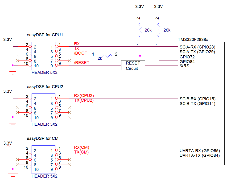
Defino series TMS320F2838xD check below two pins at the reset to decide the booting mode.
|
Boot Mode |
GPIO72 |
GPIO84 |
|
(Default boot mode select pin 1) |
(Default boot mode select pin 0) | |
|
Parallel IO |
0 |
0 |
|
SCI / Wait Boot |
0 |
1 |
|
CAN |
1 |
0 |
|
Flash / USB |
1 |
1 |
Since easyDSP uses two kinds boot modes, SCI boot mode (RAM boot) and flash boot mode. Below connection is recommended between easyDSP and MCU.

You need to use three
easyDSP pods to communicate with CPU1, CPU2 and CM all.
The easyDSP
connected to CPU1 should use SCI-A
(GPIO28 and 29 fixed).
The easyDSP connected to CPU2 can use either SCI-B, SCI-C
or SCI-D but easyDSP recommends to use SCI-B as default in its source file.
The easyDSP connected to CM should use UART.
easyDSP uses GPIO84/85 in its source
file.
In case you uses another
GPIO pins for CPU2 and CM, the hardware connection and
easyDSP source file (easyDSP_SCI_Init function in the file
of easy28x_DriverLib.c or
easy28x_bitfield.c)
should be
modified accordingly by yourself.
- Factory
default setting is assumed (Don't change it)
- Power pin (#4) of
easyDSP 5x2 header should be connected to 3.3V
- TX/RX pins are directly connected to
MCU pins
- In case there is a reset
IC between easyDSP /RESET and MCU /XRS, it should transfer easyDSP /RESET signal
to MCU /XRS within 0.5sec.
- In case you insert
buffer IC between easyDSP header and MCU, place buffer IC directly to easyDSP
header so that all resistors can be connected to directly MCU
- /RESET pin is connected to reset generation circuit of MCU board
(Time duration of /RESET pin is around 500msec)
- In case you use pull-up
resistor to each pin, the value of pull-up resistor should be higher than a few
kilo ohm since there is 100Ω series resistor inside easyDSP pod
-
You can use the boot pins (GPIO72, GPIO84) in your
program
Please be careful when you use
your own pull-up or pull-down resistor on the easyDSP signal pins. Please use
appropriate filter circuit to your reset generation circuit to prevent
unintentional reset generation.